An Introduction to Passive Athermalization
Thermal Defocus | Achromatic & Athermal Doublet Equations | Graphical Method for Choosing Achrotherm Glass and Housing Materials
For applications prone to temperature fluctuations, it is important to develop an athermal optical system: an optical system that is insensitive to an environment’s thermal change and the resulting system defocus. Developing an athermal design, which is dependent on the Coefficient of Thermal Expansion (CTE) of the materials and the change in index with temperature $ \left( \tfrac{\text{d}n}{\text{d}T} \right) $, is especially critical in the infrared. The $ \tfrac{\text{d}n}{\text{d}T} $ of most IR materials is orders of magnitude higher than those of visible glasses, creating large changes in the refractive index. Additionally, while optical systems are often designed in air, the housing material is also sensitive to thermal change and should be addressed when considering an athermalized design.
Thermal Defocus
The expansion and contraction of a material due to tempera ture changes is governed by a material’s coefficient of thermal expansion, $ \small{\alpha} $, which has units of $ \small{10^{-6}} \tfrac{\text{m}}{\text{K}} $, $ \small{10^{-6}} \tfrac{\text{m}}{˚ \text{C}} $, $ \small{\tfrac{\text{ppm}}{\text{K}}} $, or $ \small{\tfrac{\text{ppm}}{˚ \text{C}}} $. The change in length $ \small{ \left( L \right)} $ of a material due to a temperature change is given by Equation 1.
Thermal defocus is the change in the focus position on axis with temperature changes due to the variation of the index of refraction with temperature $ \left( \tfrac{\text{d}n}{\text{d}T} \right) $ and the expansion of the material. The analogous equation quantifying the change in focal length of a lens in air with temperature is given by Equation 2, where $ \small{\beta} $ is the therm-optic coefficient.
$ \small{\beta} $ can be defined using Equation 3, where $ \small{\alpha_g} $ is the CTE of the glass. The equation for $ \small{\beta} $ should include a term for changes in air index of refraction with temperature, but since this term is small compared to the material $ \left( \tfrac{\text{d}n}{\text{d}T} \right) $ values in the IR, it has not been included here. This approximation should not be used in the visible since the effects of air have more of an influence on the therm-optic coefficient than in the IR.
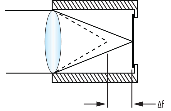
For a lens mounted in a housing with a coefficient of thermal expansion, $ \small{\alpha_h} $, the change in the focus location is a combination of the change in focal length of the lens and the change in the image plane location due to the housing expansion, as shown in Equation 4 and Figure 1. If the change in housing length is equal to the change in focus due to the lens, then the defocus is zero, and the system is considered athermal.

Figure 1: Defocus $ \small{ \left( \Delta f \right)} $ of a Lens in a Metal Housing with a Change in Temperature $ \small{ \left( \Delta T \right)} $
Achromatic & Athermal Doublet Equations
A common optical element is the achromatic doublet, which uses a positive and negative element of different materials with equal and opposite amounts of chromatic aberration to correct for color. Assuming an element is in air, the $\small{{\nu}}$-number (inverse dispersion) for an arbitrary waveband defined by the longest, shortest, and middle wavelength is given by Equation 5. If Equations 6 and 7 are satisfied, the result is an achromatic doublet. The optimal solution is one that has two elements with the largest $\small{{\nu}}$-number difference: $ \small{ \Delta \nu } $.
A larger $ \small{ \Delta \nu } $ results in longer focal lengths (lower power) and shallower radii (reduces aberrations and increases optical performance). By looking at the glass map, it is simple to visually select a crown and flint glass that has a large $\small{\nu}$-number difference. Analogously, we can use the inverse of the therm-optic coefficient (equation), usually called the thermal $\small{\nu}$ number, in our achromatic equations to design an athermal doublet (Equations 8 and 9). If we design a doublet where the achromatic doublet and athermal doublet equations are all satisfied (Equations 6-9), the result is an achrothermic system: a system that is both achromatic and athermal (Equation 10).
By plotting the thermal $\small{\nu}$-number $ \small{\left( \nu_T \right)} $ vs. the color $\small{\nu}$-number, we can visually identify two materials that can be used to develop an achrothermic system. Given the equation for a line ( $ \small{y = mx + b} $, where $ \small{m} $ is the slope and $ \small{b} $ is the y-intercept), we see that if we set the y-intercept equal to zero and choose a material $ \left( \nu_1, \, \nu_{T1} \right) $, the slope is $ \small{m} = \tfrac{\nu_{T1}}{\nu_1} $. From the doublet achrotherm equation, we know we want the slope of two different materials to be equal in order to achieve color correction and athermalization; any two materials that can be connected by a line that passes through the origin will provide an achrothermic solution. As shown in Figure 2, IG5 and AMTIR1 would provide a near-achrothermic solution in air for the LWIR (8 - 12μm). Note: The graph does not take into account the expansion of any mechanical housing of the system.

Figure 2: Sample $ \small{\nu_T} $ vs. $ \small{\nu} $ Chart for the LWIR (8-12μm)
Graphical method for choosing achrotherm glass and housing materials
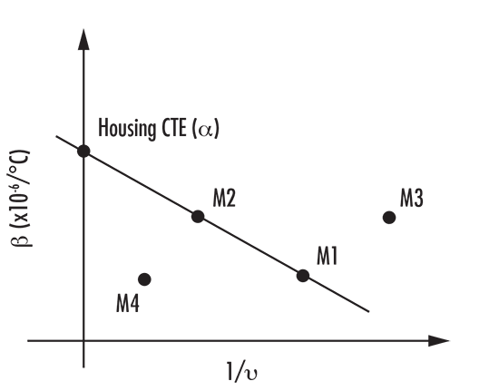
An alternative to plotting the thermal $\small{\nu}$-number $\left( \small{\nu_T} \right) $ vs. the color $\small{\nu}$-number, involves plotting the therm-optic coefficient $\left( \small{\beta} \right) $ vs. the inverse color $\small{\nu}$-number.1 This method not only helps identify two available optical materials, but also helps identify the CTE of the housing material required for a housed achrothermic solution. As shown in Figure 3, the y-intercept provides the required housing material via a line that extends through two materials and crosses the y-axis. In the case that a single housing material with the required CTE is unavailable, the required CTE can be achieved using a bimetallic housing or alternative mechanical mounting solution.

Figure 3: Generic Athermal Glass Map Plotting $ \small{\beta} $ vs. $ \tfrac{1}{\nu} $
It is important to note that this method still assumes that the $ \tfrac{\text{d}n}{\text{d}T} $ of air is minor compared to that of the optical materials; while this is true for infrared systems, the $ \tfrac{\text{d}n}{\text{d}T} $ of air must be considered for systems operating in the visible spectrum. For more details on these and other graphical methods for athermalization, please refer to the sources listed.
Note: For these equations, the power of the elements in the system is at the center of the waveband being used and the index used is at the reference wavelength.
References
- Schwertz, Katie, Dan Dillon, and Scott Sparrold. "Graphically Selecting Optical Components and Housing Material for Color Correction and Passive Athermalization." SPIE Proceedings Vol. 8486: Current Developments in Lens Design and Optical Engineering XIII, October 11, 2012.
- Schwertz, Katie, Adam Bublitz, and Scott Sparrold. "Advantages of Using Engineered Chalcogenide Glass for Color Corrected, Passively Athermalized LWIR Imaging Systems." SPIE Proceedings Vol. 8353: Infrared Technology and Applications XXXVIII, May 31, 2012.
Bibliography
1 Tamagawa, Yasuhisa, Satoshi Wakabayashi, Toru Tajime, and Tsutomu Hashimoto. "Multilens System Design with an Athermal Chart." Applied Optics 34, no. 33 (December 1, 1994): 8009-013.


or view regional numbers
QUOTE TOOL
enter stock numbers to begin
Copyright 2023 | Edmund Optics, Ltd Unit 1, Opus Avenue, Nether Poppleton, York, YO26 6BL, UK
California Consumer Privacy Acts (CCPA): Do Not Sell or Share My Personal Information
California Transparency in Supply Chains Act